ARDUINO PROGRAMMING
- aqilahqcheng0320
- Dec 27, 2021
- 4 min read
Programming of Arduino board on Tinkercad
Input devices
Something I noticed when i am interfacing the input devices is that, a serial monitor is added in to measure the amount of volts passes through the wires each time a new component is added. Input devices are often simple components such as pushbuttons and switches. Additionally, input devices is one that provides data to get a response or output.
Something I noticed when i am interfacing the input devices is that, a serial monitor is added in to measure the amount of volts passes through the wires each time a new component is added. Input devices are often simple components such as pushbuttons and switches. Additionally, input devices is one that provides data to get a response or output.
(A). POTENTIOMETER ANALOG INPUT
Interface a Potentiometer Analog Input to Maker Uno board & measure its signal in serial monitor Arduino IDE


pinmode () function: to indicate the inputs (A0) and outputs (whichever pin is used) of the Arduino Uno.
analogRead function: to listen to the pin A0 state, to read a signal
// function: comments to clarify what each code is doing
delay(sensorValue) function: instead of pausing for a fixed amount of time, the value passed to the delay function will change as the knob of the potentiometer is turned
(B). INTERFACE AN LDR
Interface an LDR to maker UNO board & measure its signal in serial monitor Arduino IDE


pinmode () function: to indicate the inputs (A0) and outputs (pin 9) of the Arduino Uno.
Serial.begin(9600) function: establishes serial communication between Arduino board and another device. 9600 is used as it is a baud rate. This number is used as it is the same for both the Arduino board and the connected device.
map photosensor to range 0 to 255:as LEDs work in a range of 0 to 255 the range of the LDR (photosensor) should be the same as well for it to function
photosensor = analogRead (A0): LDR is connected to A0 on the Arduino board
Serial.println (photosensor) function: Prints data to the serial port
analogWrite() function: Used to update status on pins, to output a signal
// function: comments to clarify what each code is doing
delay(1000) function: pausing for a fixed amount of time (1000 milliseconds)
Output devices
When carrying out the output devices coding, I learnt that an output device is one that is being controlled by a processor. LEDs is a type of a simple output device but an output device can also be motors. These common output devices are commonly associated with digital outputs. I too realise that output devices often transform electrical energy to light , sound or mechanical energy.
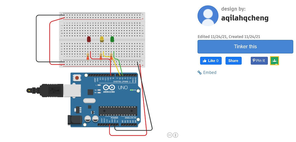
(A). INTERFACE 3 LEDs (fading)
Interface 3 LEDs (red,yellow,green) to maker UNO board and program it to perform something (fade)


pinmode () function: to indicate the outputs (pin 9,6,5) of the Arduino Uno, signals are being sent to an LED (pin 9,6,5)
for (brightness = 0; brightness <= 255; brightness += 5): brightness increases from 0 to 255 in increments of 5
for (brightness = 255; brightness <= 0; brightness += 5): brightness decreases from 255 to 0 in multiples of 5
analogWrite() function: Used to update status on pins, to output a signal
// function: comments to clarify what each code is doing
delay(30) function: pausing for a fixed amount of time (30 milliseconds)
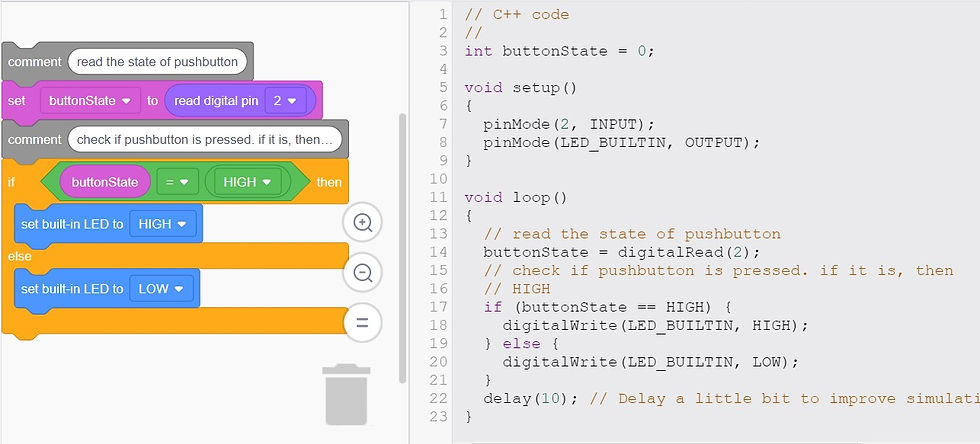
(B). INTERFACE DC MOTOR (with push button)
Interface the DC motor to maker UNO board and program it to on and off using a push button on the board


pinmode () function: to indicate the inputs (pin 2) and outputs (whichever pin is used) of the Arduino Uno.
// function: comments to clarify what each code is doing
delay(10) function: pausing for a fixed amount of time (10 milliseconds) to improve simulation process
buttonState = digitalRead(2): To listen to the pins state
if (buttonState == HIGH) {
digitalWrite (LED_BUILTIN, HIGH) ;
} else {
digitalWrite (LED_BUILTIN, LOW) ;
} : evaluates a condition using comparison operators (<,>,== etc) if the requirements is met, the codes in the brackets are executed
Here is the compiled source codes!
The first problem that I faced while doing using Tinkercad was on how to modify my codes to meet the expected requirements as most videos did not use multiple LEDs for their circuit. I easily overcome this by using my previous knowledge that I have acquired from our first lesson on Arduino where we were initially introduced to coding. I referred back to my pre-practical individual assignment that I did to refer to ensure that I am using the appropriate codes where needed.
The second problem i faced was on how to connect the LDR to the board and make it work. But with the help of videos online, I managed to set it up correctly and efficiently. I also learnt that the resistance for the resistor differs when using an LDR compared to that of a resistor for an LED.
REFLECTION:
In this week's assignment, we were introduced and tasked to use Tinkercad which is an online version of an Arduino board where all components (wires, breadboard, LED, etc) are readily available for us to use and connect to start a virtual simulation. I was tasked to simulate multiple simulations each with a different component which required different codes and inputs / outputs for it to work.
This practical is crucial as it will be efficient for me to simulate my projects online to ensure that it runs smoothly and it allows me to make any amendments without the need to reassemble everything before I confirm and finalise on my codes as well as component orientation and fix it up in the lab. Tinkercad is interesting and amazes me as it is so easy and reliable to use. Tinkercad is so cool too as I can simulate multiple simulations without any restrictions 😜
Initially when I read the task requirements for this week, I got demoralised to complete it as I am supposed to use a software that I have never heard of or seen before 😖 But, after completing my first ever simulation, I realised how easy and engaging it is to use Tinkercad. Now since I have already learnt the basics, I would be able to easily figure out how to create more complicated simulations on the software for my projects!


Comments